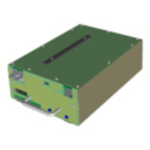
JNR-100-004B JNIOR 410 (Includes the PSA-120-125 Power Supply)

Integ

(No reviews yet) Write a Review
MSRP: $1,280.00
$562.50
(You save $717.50 )
SKU:
JNIOR JNR-200-003B
Shipping:
Calculated at Checkout
Adding to cart… The item has been added

Product Overview

Available by special order.  Allow extra time for processing and shipping.

JNR-100-004B JNIOR 410 (Includes the PSA-120-125 Power Supply)

Power

Any power supply can be used to power the JNIOR as long as it is able to supply 12 – 24 volts at at least 1 amp. The JNIOR itself only uses around 400 milliamps but the current usage rises are outputs are turned on or expansion modules are connected.

The Power connector has 4 terminals. There are extra terminals so that you can share the power supply to apply power to output circuits. Care must be given to make sure that power is not robbed from the JNIOR.

Digital Inputs

The Digital Inputs on the JNIOR are optically isolated inputs. This provides some protection from incorrectly wired installations. The inputs require at least 1.8 volts to indicate HIGH and must fall below 1.2 volts to be considered LOW again.

The JNIOR uses hardware interrupts to detect the input transitions. The JNIOR can see about 1800 transitions per second. The iolog will only report millisecond resolution.

Digital Input transitions appear in the iolog. The iolog is NOT automatically generated on the series 4. It can be generated using the iolog command. The iolog command will generate a /jniorio.log file. If you wish to just see the iolog but not create a file then you can use the iolog -o command.

Relay Outputs

The Relay Outputs on the JNIOR are dry contact mechanical relays. You must supply voltage to the circuit when wiring through the relay outputs. The relays act like a switch. Depending on the JNIOR model you have you may be able to select whether some relays are normally open (most common) or normally closed.

The relays used inside of the JNIOR are signal relays and can handle up to 30 volts. The relays in the Power 4 Relay Output module can handle up to 10 Amp @ 120/240 Volts AC. The relays on the expansion module also have contacts for normally open and normally closed. You can wire up both side of this relay at the same time.

Relay transitions appear in the iolog. The iolog is NOT automatically generated on the series 4. It can be generated using the iolog command. The iolog command will generate a /jniorio.log file. If you wish to just see the iolog but not create a file then you can use the iolog -o command.

Serial Ports

There are two serial ports on the JNIOR. Both ports are capable of RS-232 communication. The AUX port on the JNIOR 410 can also handle RS-485. The RS-232 port is used for diagnostics in the event that the Ethernet port is no longer accessible.

The AUX port can also be used for logging communications. The same iolog command can be used to write the AUX port traffic to a log for analysis. To do this you will use the -a option, iolog -a. This command will create an /auxio.log file. As with the IO, we can optionally just output the AUX traffic and not create a log file. To do this we use the iolog -ao command.

Sensor Port

The Sensor Port allows one wire devices to be connected. The connection to the JNIOR uses an RJ12 connector but only pins 1 – 3 are used.

INTEG expansion modules implement two connections so that devices can be daisy chained. If a temperature probe or other one wire device that does not implement two connections is used, then a splitter can be used like this one from Amazon.

INTEG has a variety of expansion modules for different uses. Other one wire devices can be connected as long as there is an application written that knows how to talk to them. JANOS only natively supports INTEG expansion modules and a temperature probe.

Applications

The JNIOR has a JVM (Java Virtual Machine) in the Operating System to provide the ability to run additional logic on the JNIOR. There can be several additional programs loaded and running on the JNIOR simultaneously. A powerful interface exists to give applications fast access to JNIOR features. These applications can be written by INTEG or by an end user. INTEG can write these applications based on new features that we want to provide on based on custom specifications provided to us by an end user. End users who know java can write applications easily and effectively using their favorite Java IDE. A JAR file created by an IDE can run immediately on the JNIOR without any additional compilers or converters.

The JNIOR Model 410 is an Ethernet I/O controller and data acquisition device with 8 digital inputs, 8 relay outputs, one Ethernet port, two serial ports and one Sensor port

JNIOR 410 Data Sheet      JNIOR 410 Brochure
 
TUV Certification

Reviews

(No reviews yet) Write a Review